Integration Designer
IMan comes with several sample integrations. They show you how to build an IMan integration and demonstrate some of the product's features.
This section is a short introduction to working with the designer.
Where the step-by-step walk-throughs are
For a fuller description, see the IMan User Guide. For a step-by-step walk-through, see the training guide for your application.
Opening the Designer
-
Select Design from the menu down the left of the screen.
-
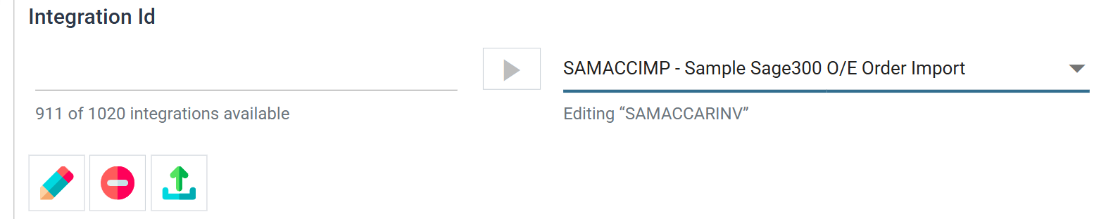
The Options tab opens first. Select one of the sample integrations from the drop-down, then press the pencil button beside the Integration Id box to load it.
The pencil button is titled Load Integration. It is disabled when the integration you chose is already open. The Editing label under the drop-down names the open integration.
-
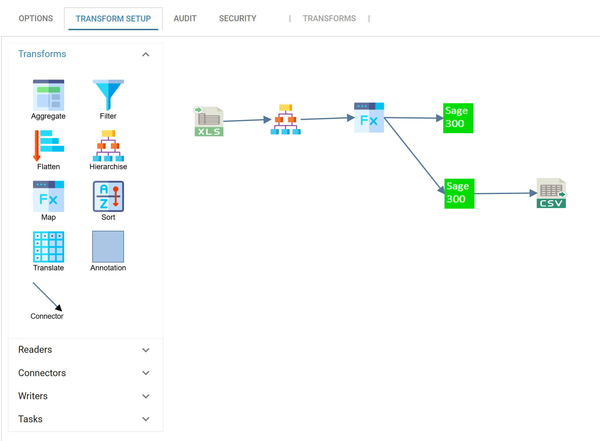
Open the Transform Setup tab to show the graphical design interface.
-
The transform palette runs down the left-hand side, in five groups: Transforms, Readers, Connectors, Writers and Tasks. To add a node to an integration, drag its icon onto the design surface.
-
The right-hand side is the design surface. You build and maintain the integration here, and define the relationships between its transforms.
Opening the Transform Setup Screen
-
The first node in an integration is typically a reader, or data source. Double-click the node to open its setup screen, where you define the node's settings. The setup screen opens as a new tab, named after the transform.
-
Each transform setup screen is divided into two panes:
- The left-hand pane holds the transform's settings, on the tabs across its top. For the reader below, the tabs are Setup, Field Mapping and Audit. The tabs vary with the type of transform.
- The right-hand pane previews the transform's results. It also shows the Trace and Audit for the same run.
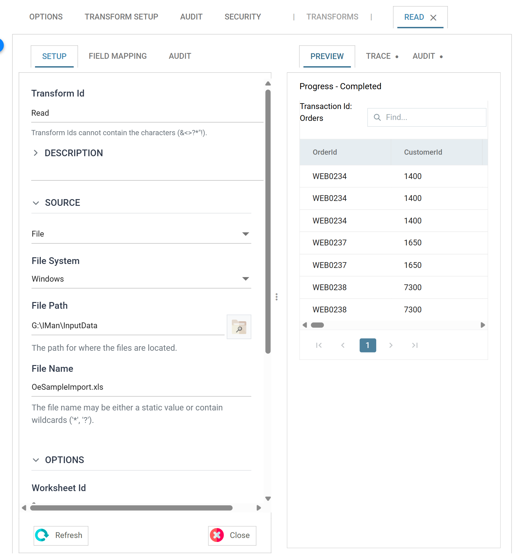
- Press Refresh to build the preview on the right. Refresh runs the transform against its data and takes a few seconds.
A transform setup screen has no Save of its own
A transform setup screen has no Save of its own. Close applies your changes to the integration held in memory. The integration's own Save button, beneath the design surface, then saves the integration.
Connecting Transforms
You connect transforms with the connector object, at the foot of the Transforms palette.
The connector is an arrow. Its head points in the direction the data flows.